
- 163 users















Pinned Items
Recent Activities
-
 After a Auto-Throttle clutch pack replacement in the nose compartment, we had a "Left FCC A/P Disconnect Switch" fault during MCDP (return to service tests).
This doesn't mean the left switch is the bad one because either switch could be the issue. The right and center FCC's can throw the same message.
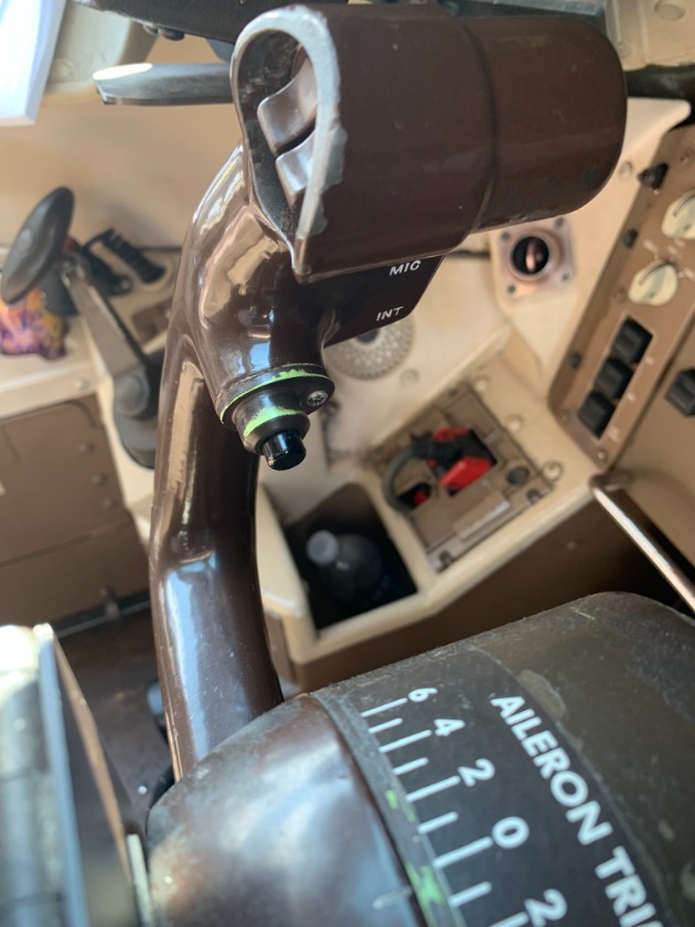
The FCC's want to see a ground on pin "F15" of the "B" plug during system tests. Unless either yoke disconnect switch is depressed, the ground should always be present.
The signal path goes through the F/O's yoke, then the Capt's yoke in series.
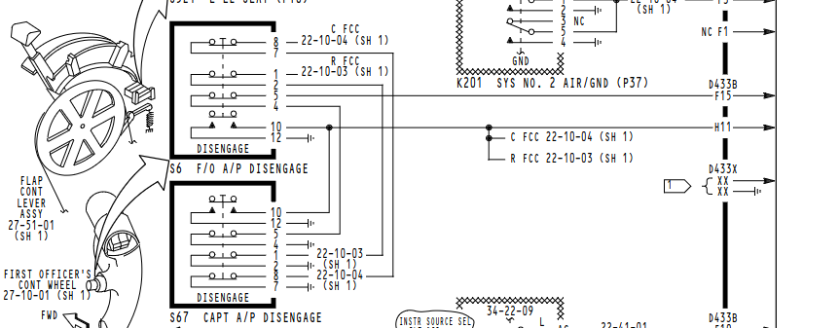
We were open to ground from the Left FCC rack. I put a tone on the wire with the "Fox and Hound".
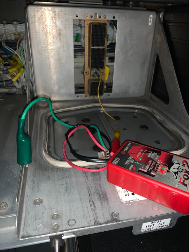
I had good tone under the F/O's yoke, but it died when making my way over the the Capt's yoke terminal block.
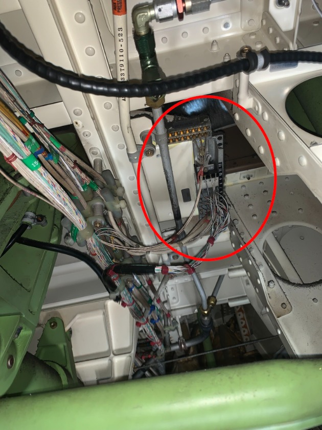
Backtracking to the area above the clutch pack we found this shit.....
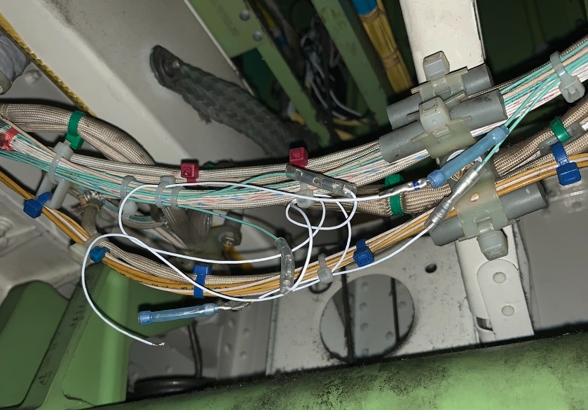
One broken wire (ours) and another jewel of a wiring repair right along with it.
Regular butt splices hooked up to bastardized environmental splices on two sets of wires with about 8 inches between each of the splices on each wire. The environmental splices didn't have the sleeve shrunk down and a crimp on one of the barrels done with flat faced Knipex pliers.
We repaired the wires properly but seriously..... WTF??
Post is under moderationStream item published successfully. Item will now be visible on your stream. -
 Looks like a brutal fix. Fuel is the worst system on the airplane by far to work on.Post is under moderationStream item published successfully. Item will now be visible on your stream.
 -
Post is under moderationStream item published successfully. Item will now be visible on your stream.
-
Please reference rotate.aero/forum/test-equipment/224-fuel-quantity-test for fuel quantity basics and test box usage.
Please reference rotate.aero/forum/767-28fuel/765-surge-tank-sensors for one example of using the test box.
There is a cable connection issue when it comes to using different manufacturer Fuel Quantity Test Units.
Some, have reverse polarity BNC connectors.
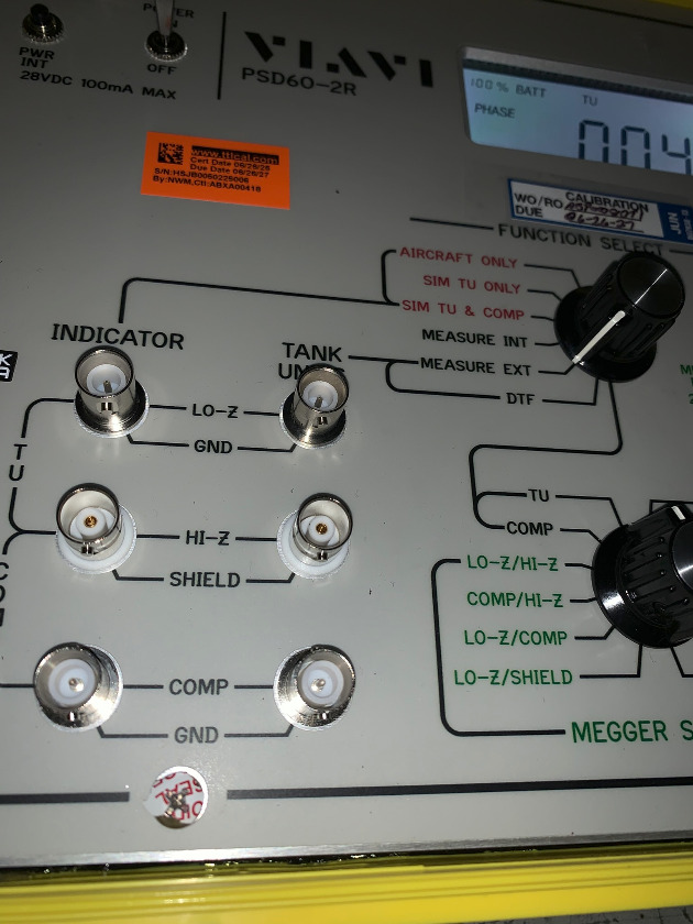
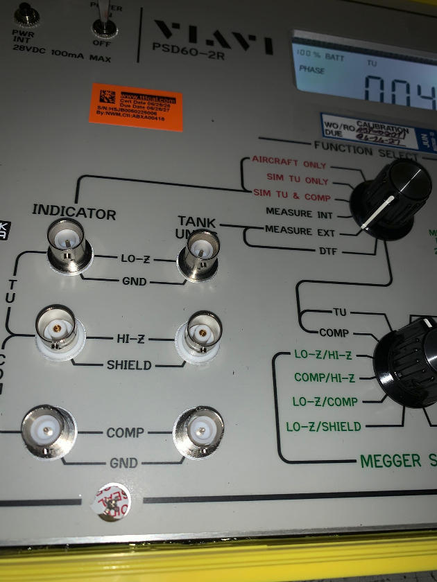
On this Viavi box, the LoZ and Comp connectors are males. The HiZ is female.
Most co-ax test cables are male on both ends, which connect to the HiZ BNC connector.
You must have a set of special cables made up (male on one end and female on the other.....
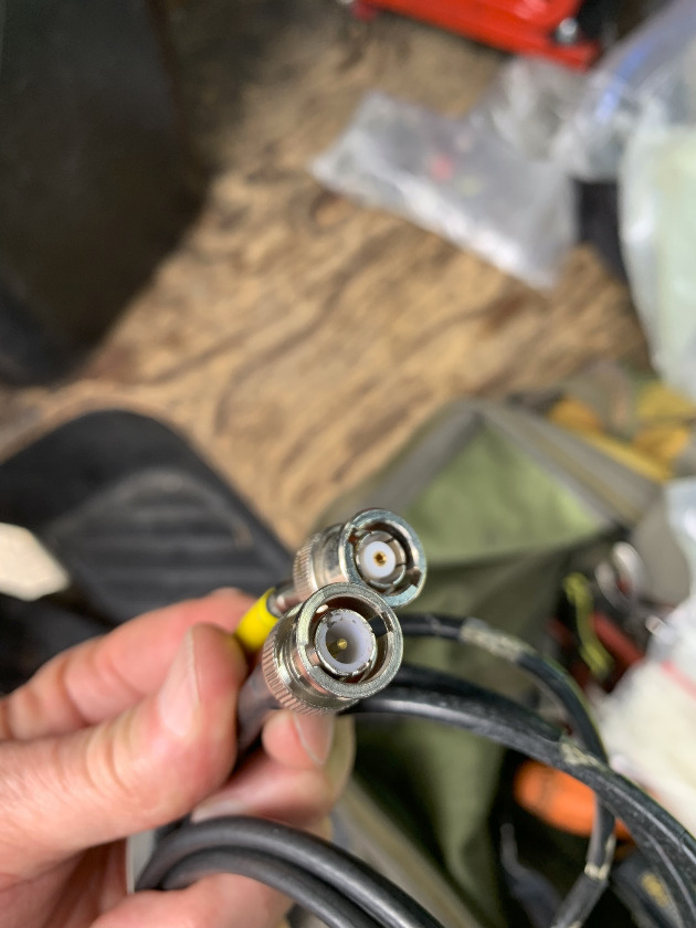
.....or what I call "gender-bender" adapters to use for the LoZ and Comp BNC's.
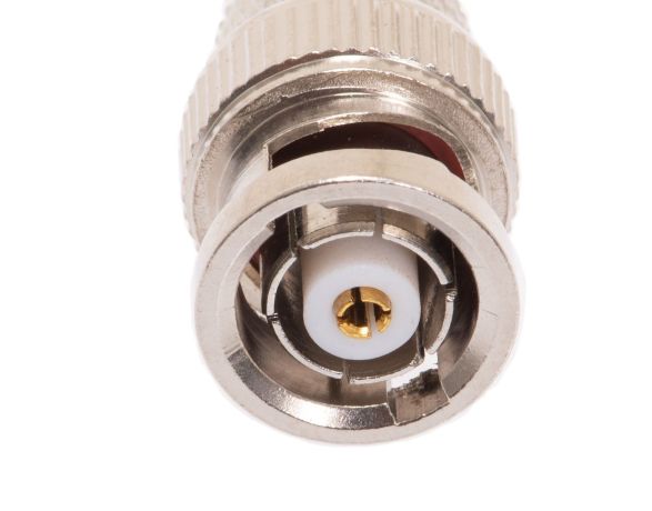
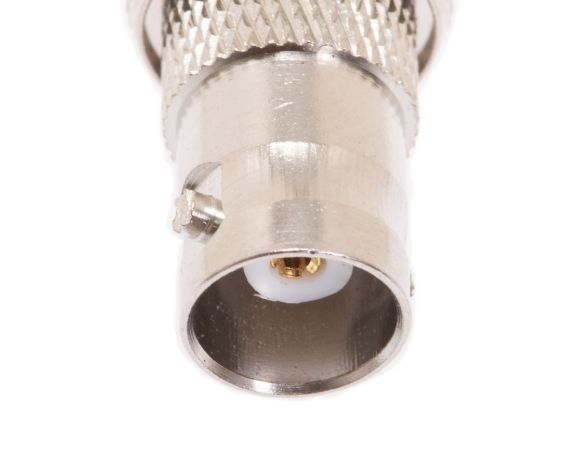
These are somewhat hard to find. I ordered some from a place called Show Me Cables .
Post is under moderationStream item published successfully. Item will now be visible on your stream. -
Please reference rotate.aero/forum/767-28fuel/401-ata-28-21-pressure-fueling for more info on pressure fueling overflow protection.
We had an aircraft that would not accept fuel (open the fueling valves) without pressing the "reset" button at the fueling panel. When this button is used protection provided by the Fuel Level Sensing Card (M586) is bypassed.
Usually, when this fault occurs you have one of the two surge tank probes not feeding a capacitance signal to the card.
There is a extender card for testing the probes.
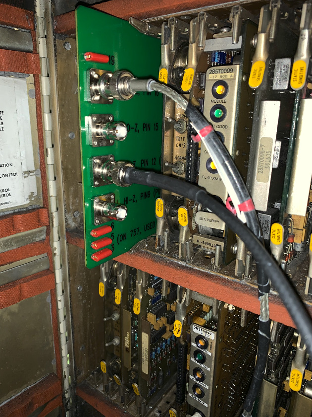
Co-ax cables are connected to a fuel quantity test box on the Hiz and LoZ "Tank Unit" inputs. (The indicator plugs are used for simulation.)
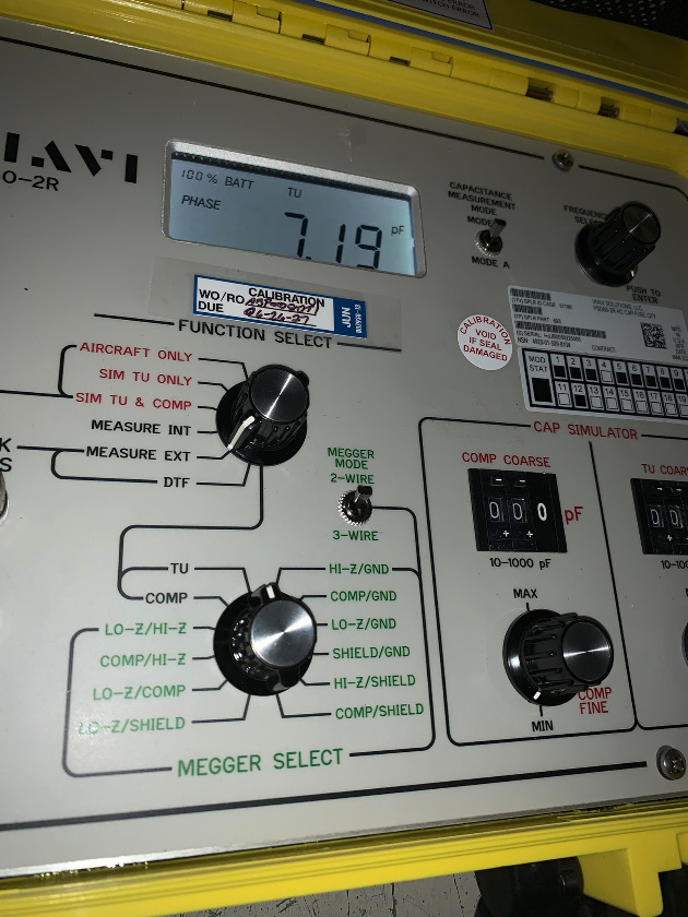
For a 767, you want to see around 7pF to 8pF. We had one reading correct and one not.
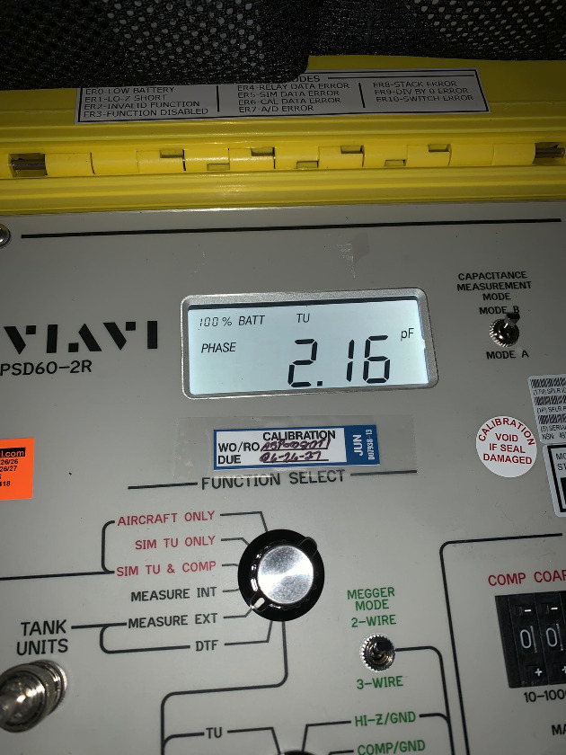
Switching from capacitance to resistance, showed a HiZ to Shield short on the low reading probe.
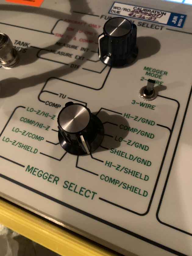
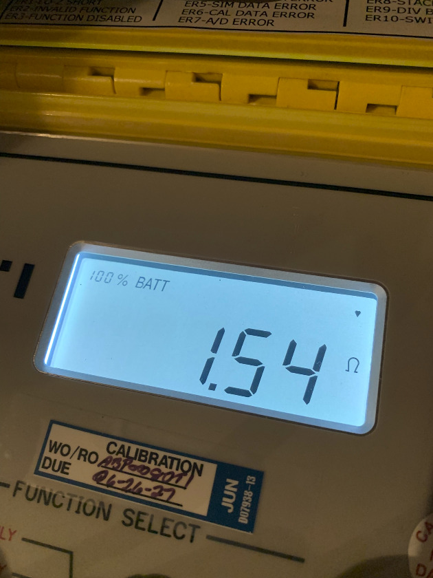
This reading (all meg readings) should be open or the high MegOhm range.
To isolate further we disconnected the probe.
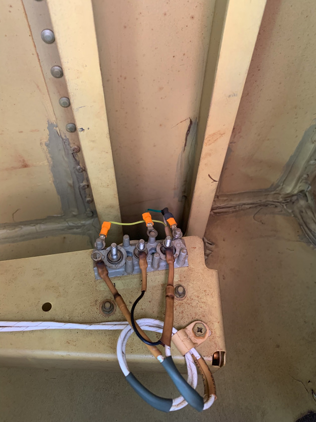
Resistance was still low. We then disconnected the plug at the wing root to isolate the wing harness. After disconnect, the resistance reading showed open.
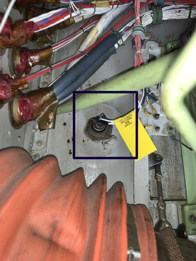
Our problem was the wing harness.
It's a tough replacement as it runs into the center tank, through the main tank, and then into the surge tank.
Post is under moderationStream item published successfully. Item will now be visible on your stream. -
Please reference rotate.aero/forum/ata24-767/343-ata-24-2...ed-power-feeder-wire for some of our previously encountered problems.
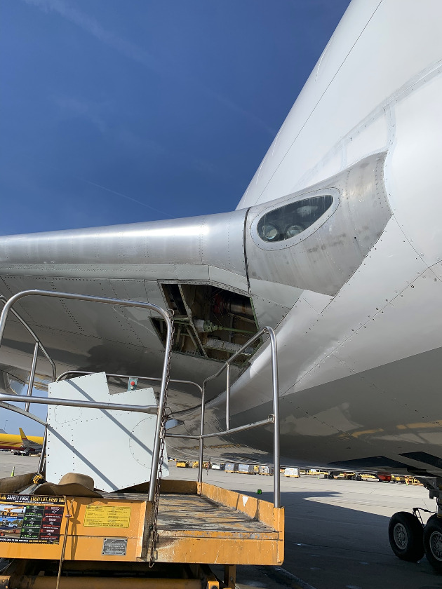
Another power feeder wire short. This time the problem was inside the pressure vessel, as we normally find these on the engine or pylon.
The BPCU (Bus Power Control Unit) faults are always the same, DP Trip (Differential Protection) and GEN/FDR Fault (Generator/Feeder).
System isolation is the first step in troubleshooting. The feeder wires from the engine IDG (Integrated Drive Generator) go to the generator contactor. There are some extra wires connected to the three big feed wires. Three (one for each phase) go to the Generator Control Unit or GCU. Removing the box from the rack isolates those wires. Two extra wires, one for a red "Bus Hot" light and a EICAS voltmeter input also need to be separated from the feeds. Removing the bulb and pulling the breaker will accomplish that.
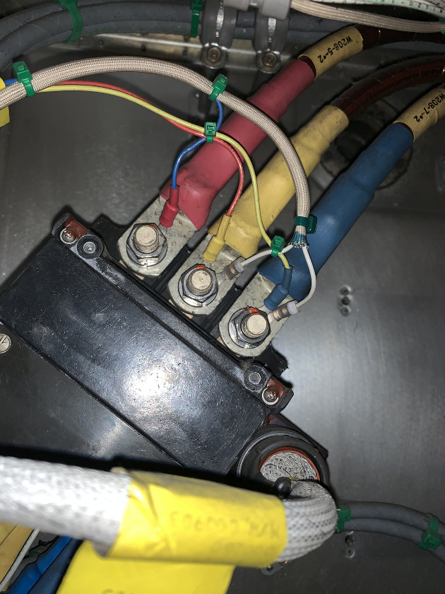
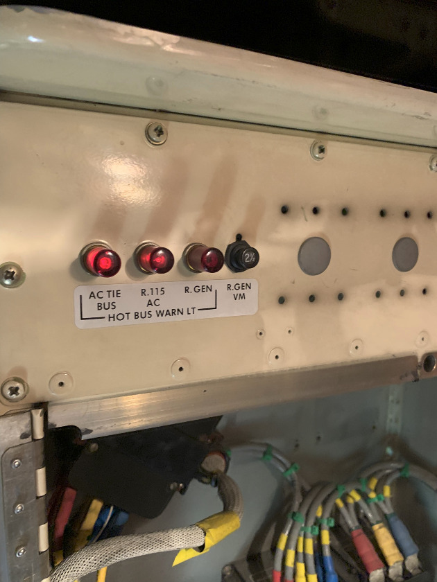
Using the megger from the generator end, we found the blue wire with the short.
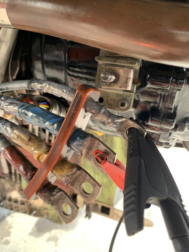
No registered meter scale and less than 1 Meg-Ohm resistance. (The meggar picked this up as a hard short, but a regular VOM showed an open circuit.)
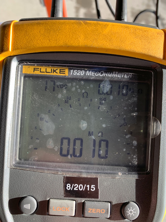
We went ahead and removed the blue feeder from the contactor just to make sure nothing else was in the system. The reading was the same.
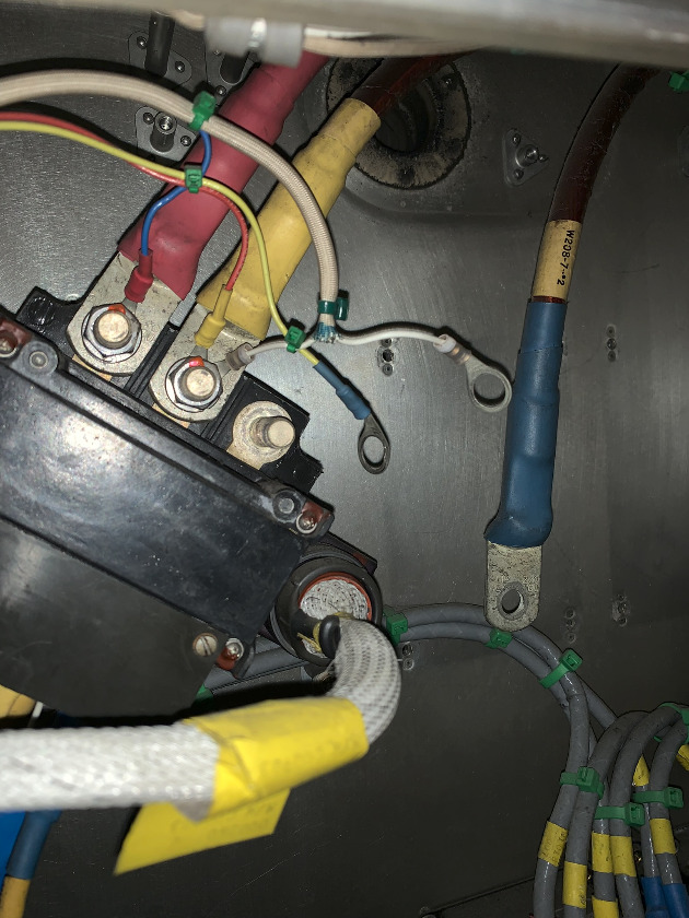
We shook all over the engine and pylon with the megger on..... no joy. Same thing with some wing leading edge panels removed. (Two hours or more)
When we started shaking the wires in the right side forward lower cargo deck, the meter started jumping.
I wonder why....
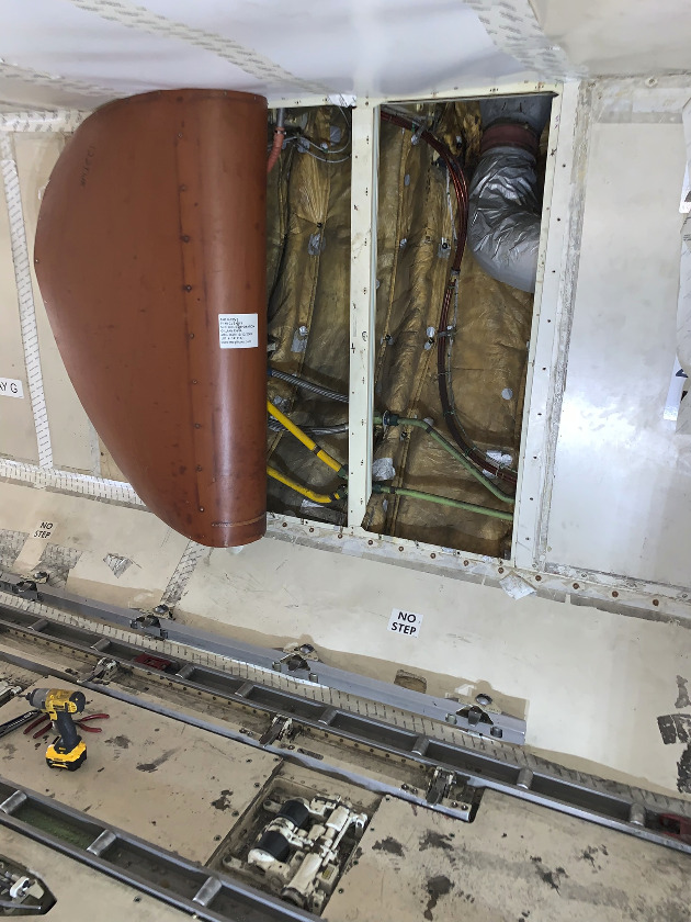
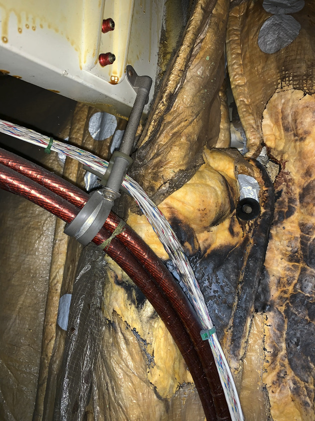
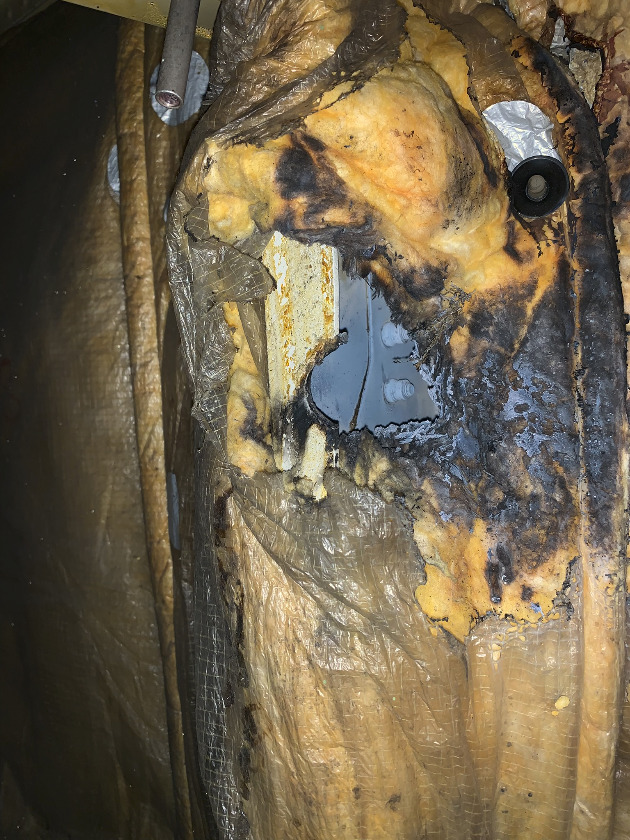
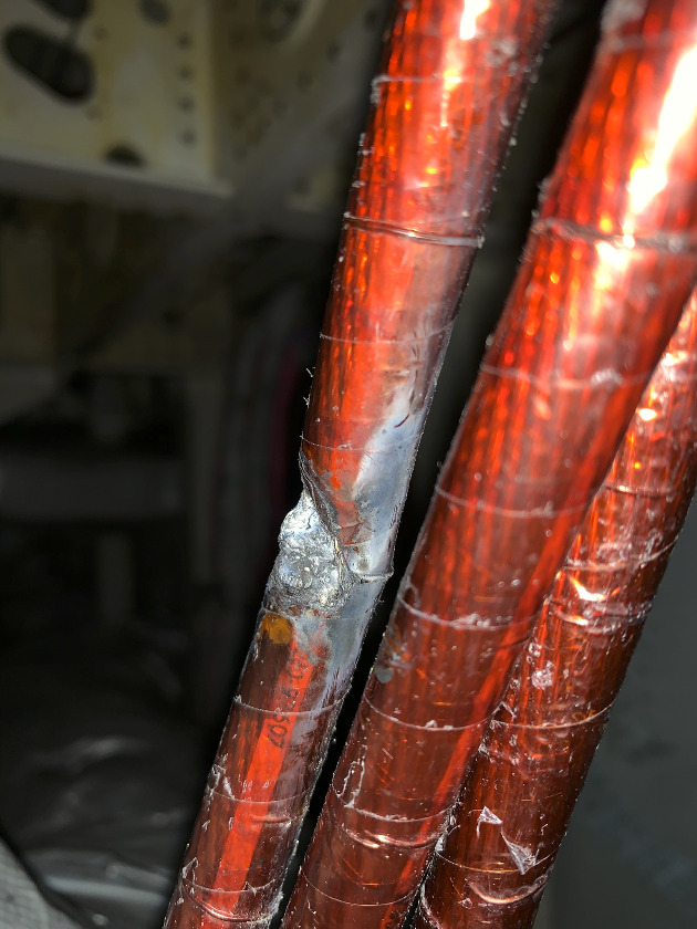
Fun Stuff!!!
Post is under moderationStream item published successfully. Item will now be visible on your stream. -
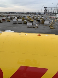
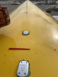
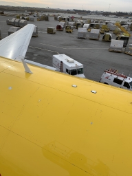
Not the same day, but still a couple pretty nice shots.....
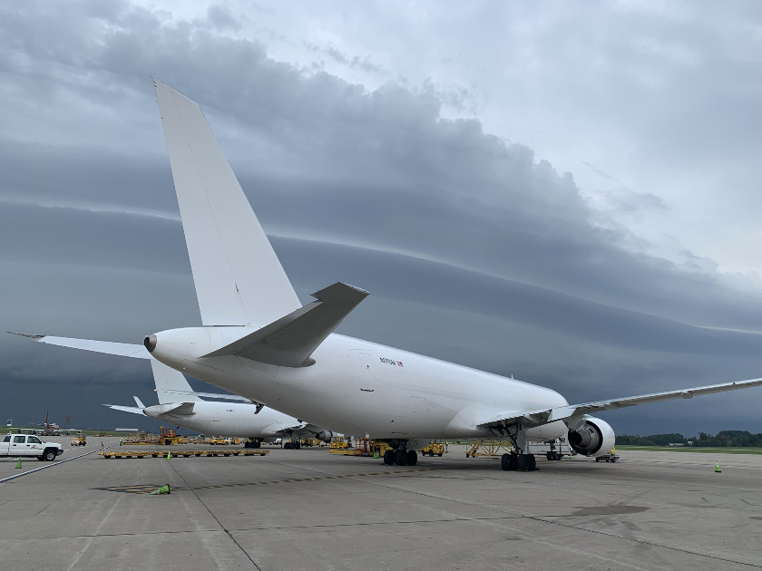
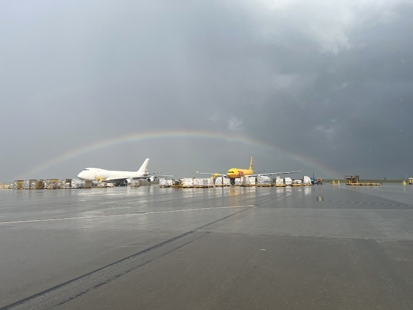
Post is under moderationStream item published successfully. Item will now be visible on your stream. -
Post is under moderationStream item published successfully. Item will now be visible on your stream.
-
Nice work Mark a lot would forget about the parallel resistor formulas.Post is under moderationStream item published successfully. Item will now be visible on your stream.
-
Servo valve explanation.....
Post is under moderationStream item published successfully. Item will now be visible on your stream.
There are no activities here yet
Rotate Aero Users



Random acts of kindness are contagious!!
Don't have an account?
Register now to join the community!
©
2026
Rotate.Aero